Automotive ergonomics focuses on the role of human factors in the design and use of automobiles. This includes analysis of accommodation of driver and/or passengers; their comfort; vision inside and outside vehicle; control and display design; pedal behaviour , information processing and cognitive load during driving etc.
In the present module attempt will be made to discuss various physical aspect of occupant packaging for providing comfortable driving posture, clearance dimensions, proper view field, easy reach of the controls etc. to the driver.
This module highlights the following:
• Spatial accommodation
- Seating Position
- Leg Room
- Head Clearance
- Lateral Clearance
• Sitting comfort /discomfort
• Reach and limitations of human
• Visual field and Visual Obstruction
To establish the required interior space, and arranging the interior and structural components, the design methods relies on the human factors data base through years of research and practical applications.
The anthropometry for automotive design is consistent with the driver and passenger safety, comfort, convenience and accommodation. The study of human capabilities and limitations gives the measurements for designing automobiles.
Anthropometric Measurements for Automotive Ergonomics:
Automobile is designed as per the anthropometry of the targeted user population. Measurement process can be broadly classified into two categories.
Conventional Static Measurements:
The measurements taken on human body with the subjects in rigid, standardized position (fig.10). They are typically length, width, height and circumferences. These measurement includes standing height, seated height, seated eye height, upper leg length, knee height, seat length, upper and lower arm length, reach (total arm length), shoulder width, hip or seat width, weight, etc.
These measurements are referenced to non-deflecting horizontal or vertical surfaces supporting the subject.

Fig 10. Conventional static measurements
(Image Source: Peacock and Karwowski, 1993)
Functional Task Oriented Measurements:
The measurements are taken with the human body dimensional co-ordinates x, y, z with respect to body land marks as reference points. at work or motion in the workspace (fig. 11). Typically they are represented in three dimensional co-ordinates x, y, z with respect to body land marks as reference points:

Fig 11. Functional task oriented measurements
(Image Source: Peacock and Karwowski, 1993)
In automobile design, at first the position of the occupant/driver with comfortable driving posture on the seat is defined. Then all other components are arranged around the driver to provide easy reach, vision and control operations.
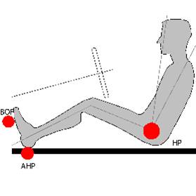
Few reference points e.g. H-point, BOF, AHP etc. are used as standard practice to define driver’s position while SRP, NSRP and SgRP are generally used to define seat position in relation to driver.
• H-point ( Hip pivot): Mid point of the line connecting two hip joints.
• BOF (Ball of Foot): Ball joint of Foot.
• AHP (Accelerator Heel Point): position of the heel while placed on the accelerator.
• SRP (Seat Reference Point): Intersection point between midline of compressed seat back and compressed seat pan.
• NSRP (Neutral Seat Reference Point): 50th percentile person selected SRP.
• SgRP: 95th percentile person selected SRP.
These landmarks (fig.12) relate the occupant to components in the vehicle interior such as foot controls, seat and floor. For example, the foot is related to the ball of foot and accelerator heel point, where as hip, elbow and shoulder width are related to the h-point location.

Fig. 12 Landmarks for measurements
To accommodate wide range of target population, 5th and 95th percentile anthropometric data are used in general.
Seat Track Travel Limit:
Seat track travel limit is decided in such a way so that individuals with smaller body dimensions as well as larger body dimensions can seat comfortably on the seat and can access all the controls including accelerator, break and clutch. Seat track travel limits in forward-backward and upward-down ward direction are decided as per operational requirement.
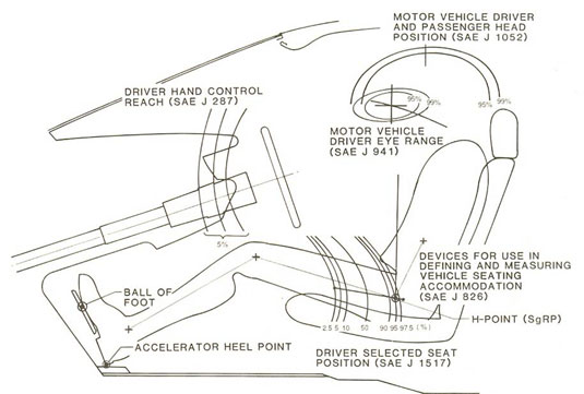
Fig. 13 depicts forward-backward movement of the seat as per the different percentile driver selected seat position (SAE- J1517).

Fig. 13. SAE recommended occupant packaging
(Image Source: Peacock and Karwowski, 1993)

